Registers and Register Transfers
Registers, Microoperations and Implementations
Register: a collection of binary storage elements
In theory, a register is a sequential logic which can be defined by a state table。
2-bit Register

State table:

当位数增加时,状态表会变得非常大,因此需要一种更好的方式来描述寄存器。
设计寄存器的方法:
-
Add predefined combinational circuits to registers 给寄存器添加预定义的组合电路
Example: To count up, connect the register flip-flops to an incrementer
-
Design individual cells using the state diagram/state table model and combine them into a register 将寄存器分解为单独的单元,然后将它们组合成寄存器
Register Storage and Load Enable
寄存器功能:
-
Load is a frequent name for the signal that controls register storage and loading
- Load = 1: Load the values on the data inputs
- Load = 0: Store the values in the register
需要实现数据保持,在 Load 信号控制下进行数据存储和加载。(低电平有效)
Solution:
-
Registers with Clock Gating

\(clk_G = \overline{Load} + clk\)
缺点:出现时钟歪斜。不应出现在同步电路中。
-
Registers with Load-Controlled Feedback
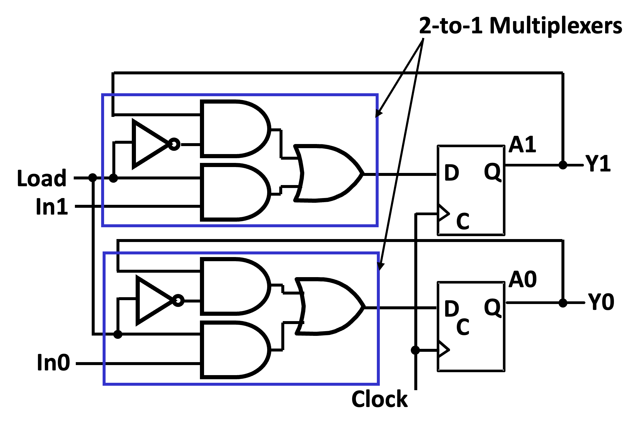
使用多路复用器实现 load 控制的数据保持。
Register Transfer Operations
The movement and processing of data stored in registers.
Three basic components:
- set of registers
- operations
- control of operations
Elementary Operations: load, count, shift, add, bitwise "OR", etc, called microoperations.
Control of Operations: a set of signals that specify the microoperations to be performed and the registers in which they are to be performed. 控制哪些寄存器之间做什么操作。
Register Notations
- Letters and numbers: 表示寄存器标识。
- Parentheses
(): 表示寄存器的某一位或某一区间的位,如 \(R_1(0)\)。 - Arrow
<-: 表示寄存器内容的传输,如 \(R_1 \leftarrow R_2\)。 - Brackets
[]– Specifies a memory address 表示内存地址。如 \(R_1 \leftarrow M[PC]\) 表示把 PC 命令的内存地址存储到 R1 中。
Conditional Transfer
K 控制传输的条件,当 K 为 1 时,传输发生。

Example
If (K1=1) then (\(R_2 \leftarrow R_1\)) 写成 K1: \(R_2 \leftarrow R_1\)。
即 K1 控制 R2 的接受,R1 的内容始终已经准备好,当 K1 为 1 时,R2 接受 R1 的内容。
Arithmetic Microoperations


Shift Microoperations:

Register Cell Design
Assume that a register consists of identical cells.
Each cell has:
- a register
- Data inputs to the register
- Control input combinations to the register 控制信号
- A set of register functions 对应每个控制信号的操作
- A hold state specification 保持状态
Example
Register A (m-bits) Specification:
- Data input: B
- Control inputs (CX, CY)
- Control input combinations (0,0), (0,1) (1,0)
- Register transfers:
- CX: \(A \leftarrow B \vee A\)
- CY: \(A \leftarrow B \oplus A\)
- Hold state: (0,0)
- Load control: Load = CX + CY
Sequential Circuit Design Approach:
Find a state diagram or state table 现态、输入、控制信号共同决定次态。
续
State Table:

Register Transfer Structures
Multiplexer-Based Transfers
Multiplexers connected to register inputs produce flexible transfer structures.
Example
R0 load 信号为 \(K_1 + K_2 \overline{K_1} = K_1 + K_2\)
Multiplexer and Bus-Based Transfers for Multiple Registers
-
Dedicated MUX-Based Transfers

开销太大。
-
Multiplexer Bus

通过总线连接多个寄存器,通过控制总线的传输来控制寄存器的传输。
优点:灵活,开销小。
-
Three-State Bus

通过三态门控制总线的传输。
Shift Registers

- Data input, \(In\), is called a serial input or the shift right input.
- Data output, \(Out\), is often called the serial output.
- The vector \((A, B, C, Out)\) is called the parallel output.
Counters
Counters are sequential circuits which "count" through a specific state sequence. They can count up, count down, or count through other fixed sequences.
- Ripple Counters: 输入接在最低有效位上(LSB),后面每一位的 clk 接在上一位的进位输出上。不是同步电路。
- Synchronous Counters: Logic is used to implement the desired state sequencing. 同步电路。
Ripple Counters
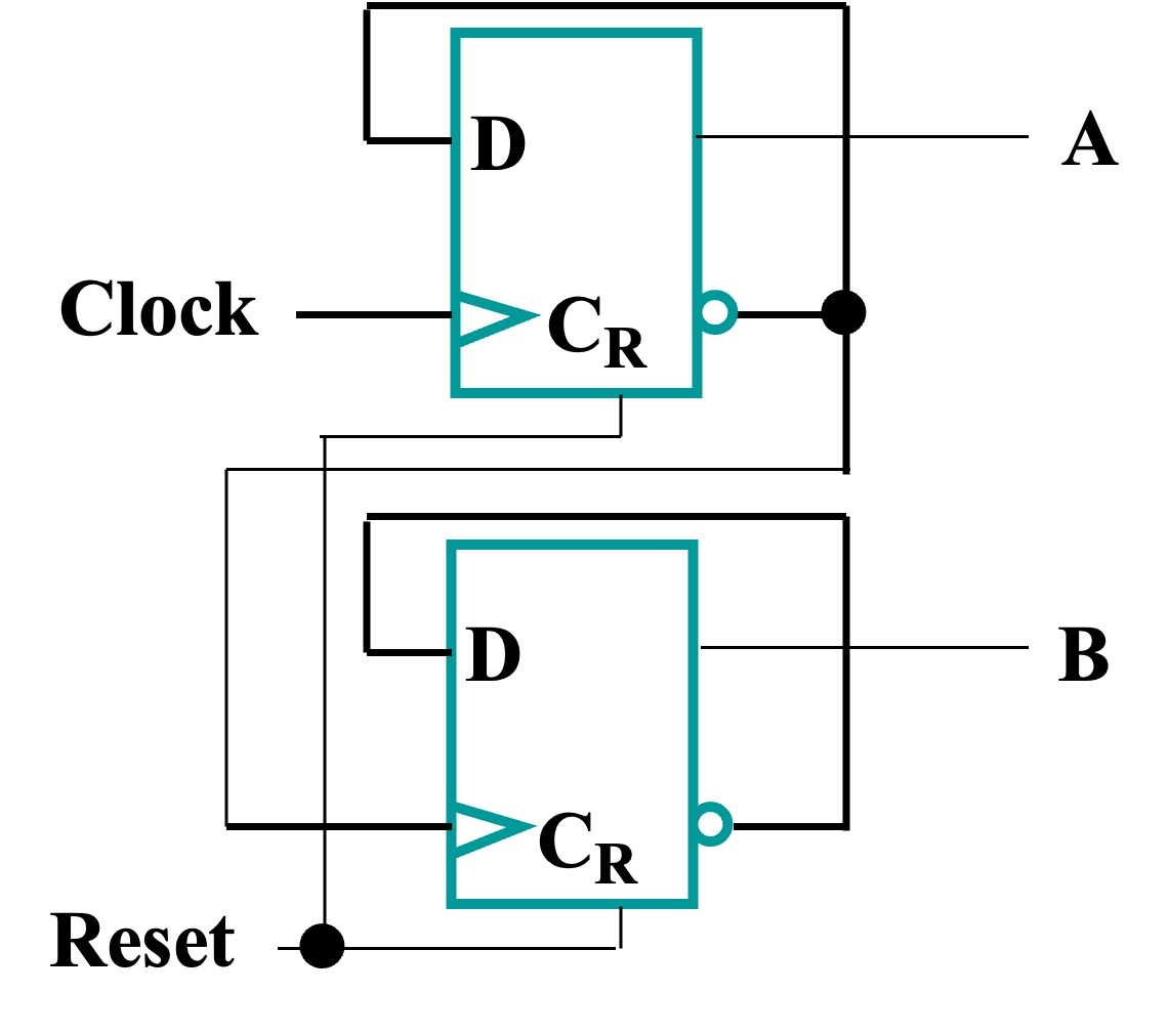
每个触发器的时钟,没有接在同一个系统时钟上,是一个异步时序电路。
Synchronous Counters

Note
使用与门信号链控制计数:
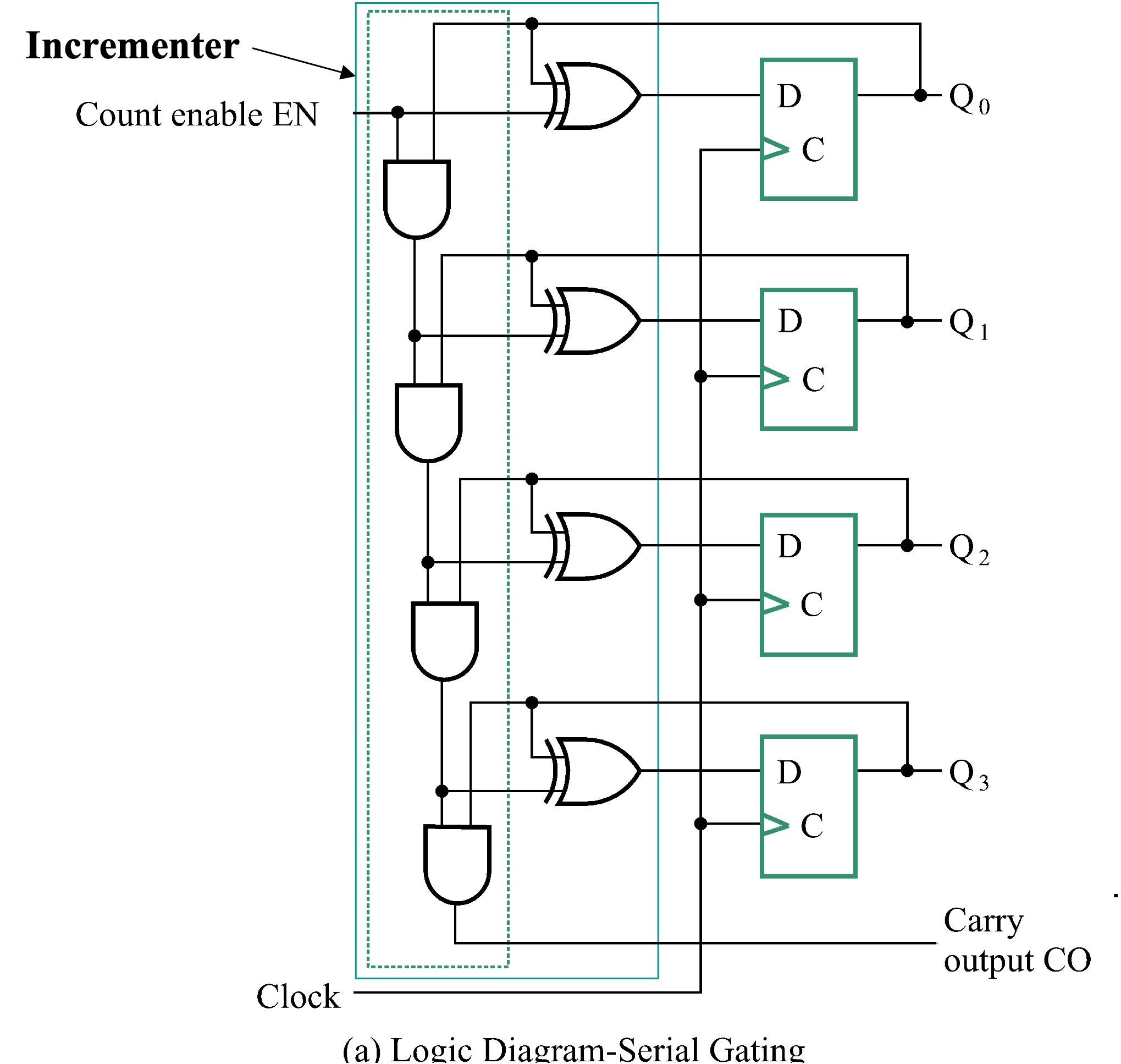
当低位全为 1 且使能信号为 1 时,高位求反。
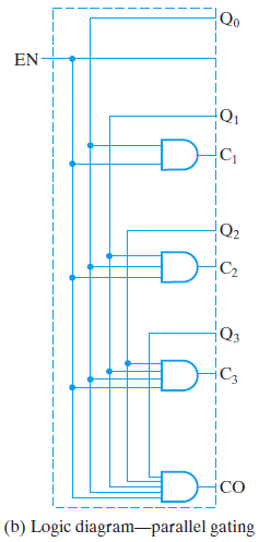
当位数增加时候,使用 look ahead 简化电路:每隔若干位,将输出使用与门接在一起。
Other Counters
- Down Counter: counts downward instead of upward
- Up-Down Counter: counts up or down depending on value a control input such as Up/Down
- Parallel Load Counter: Has parallel load of values available depending on control input such as Load
- Modulo n Counter: n 进位计数器,当计数到 n 时,回到 0,重新开始计数。
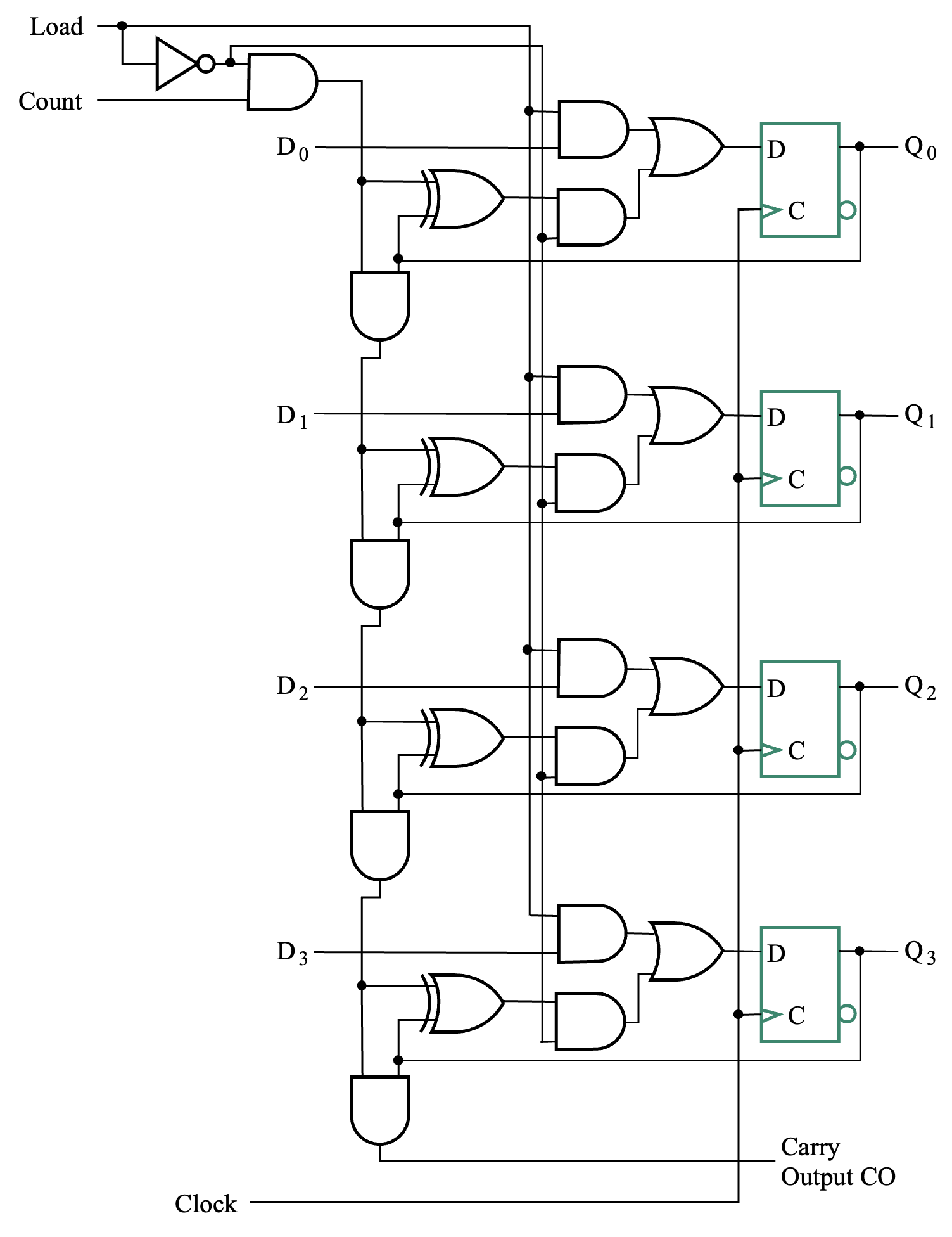
Counter with Parallel Load
Modulo n Counter
-
使用异步清零实现:

缺点:会产生很短的脉冲,可能会导致错误。
-
使用同步清零实现:提前准备好清零。

自定义初值:

从 9 开始计数到 15。
Serial Transfers and Microoperations
寄存器一次只接受一个二进制位,可以使得时钟周期更短,但是传输相同位数的数据需要更多的时钟周期。
可以使用更简单的电路实现 microoperations: By using two shift registers for operands, a full adder, and a flip flop (for the carry), we can add two numbers serially, starting at the least significant bit.
Serial Adder
